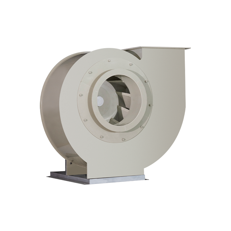
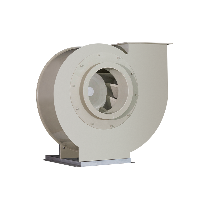
Shanghai Shujia Environmental Protection Engineering Co., Ltd. manufactures the Laboratory Anti-Corrosion Centrifugal Fan manufacturer range for laboratory exhaust systems. Each unit is a driven fluid machine that converts motor input into gas pressure, moving corrosive vapours, acid mist and odorous compounds from fume hoods, reagent cabinets and ventilation rooms into the exhaust duct network.
The fan sits inside our Laboratory Waste Gas Treatment scope together with scrubbers, adsorption boxes and PP ducting, so airflow, duct routing and downstream treatment are engineered as one train rather than as separate purchases. Founded in 2012, we run three production bases covering 40,000 m² in Jinshan District, Shanghai, China, with more than 200 staff across production, R&D, construction and service.
What We Build Into Every Anti-Corrosion Fan
Corrosive duty decides the material. We offer two wetted-path options — polypropylene (PP) and fiberglass-reinforced plastic (FRP) — and in the FRP build the casing, impeller, wind collector, belt cover and motor protective cover are all produced in FRP. The assembly is maintainable: casing, impeller, motor, pulley, bracket and transmission bearing are individually replaceable.
- Drive: pure-copper-wire motor matched to the required duty point.
- Transmission: European-standard taper-sleeve pulley for belt alignment and straightforward ratio changes.
- Bearings: NSK and SKF bearing sets for stable running under continuous exhaust duty.
- Structure: FRP casing and impeller, wind collector, belt cover and motor protective cover.
Our Range in the Laboratory Exhaust Train
The fan is the pressure source of the system, and the equipment around it defines the resistance it must overcome. We supply the full chain so that selection, interfaces and installation detail stay consistent.
| Equipment |
Function |
Interface with the fan |
| Anti-Corrosion Centrifugal Fan |
Air movement and pressure generation |
Sets the airflow the whole train must handle; outlet angle and rotation are matched to the duct route. |
| Wet Scrubber Tower |
Removal of water-soluble acid mist, ammonia and similar contaminants |
Positioned in the treatment sequence so the fan handles gas at the correct stage of the train. |
| Activated Carbon Adsorption Box |
Polishing stage for residual VOCs and odour |
Adds system resistance that must be included in the fan duty point. |
| PP Air Duct and Accessories |
Corrosion-resistant duct network, bends and fittings |
Determines actual pressure loss, which is the basis for fan selection. |
Material Options: PP and FRP
Both materials resist the acid mist, solvent vapour and ammonia loads typical of laboratory exhaust. The choice follows the gas composition, the casing size and the structural demands of the mounting position.
| Material |
Components produced |
Where it fits |
| PP |
Wetted components in polypropylene |
Laboratory exhaust duty with acid mist and general corrosive vapour, where a lighter assembly suits the mounting position. |
| FRP |
Casing, impeller, wind collector, belt cover, motor protective cover |
Larger casings and heavier duty where structural stiffness and long service life under continuous running matter. |
Outlet Angle, Rotation and Duct Fit
Laboratory buildings rarely offer a straight duct run to the roof or plant room. We supply multiple outlet-angle and rotation positions, covering left-hand and right-hand arrangements across a 0°–225° range, so the fan connects to the existing route without unnecessary bends.
- Left-hand or right-hand rotation selected against the duct approach direction.
- Outlet position set between 0° and 225° to align with the riser or horizontal run.
- Bracket and base detail adapted to floor, wall or platform mounting.
- Belt drive with taper-sleeve pulley, allowing the duty point to be trimmed on site.
Information We Use to Configure Your Solution
A fan that matches the duct network and the treatment train is defined by a small set of project inputs. These are the values our engineers work from when preparing a configuration and quotation.
| Project input |
What we need |
How we use it |
| Duty point |
Required air volume and total system resistance |
Selects impeller size, motor rating and belt ratio. |
| Gas conditions |
Contaminant type, concentration range, temperature, humidity |
Confirms PP or FRP wetted path and gasket selection. |
| Duct layout |
Route drawing, outlet direction, available plant space |
Sets outlet angle, rotation hand and bracket position. |
| Power supply |
Voltage, frequency and phase |
Specifies the pure-copper-wire motor. |
| Control interface |
Damper signal, start-stop logic, BMS or EMS interface |
Coordinates fan control with the laboratory environment control system. |
| Site conditions |
Indoor or outdoor location, ambient conditions, mounting base |
Defines protective cover, bracket and installation detail. |
| Documentation |
Nameplate data, drawing requirements, labelling language |
Prepares the delivery documentation package. |
Controls and Automation Integration
Laboratory exhaust is normally modulated rather than run at a fixed rate, because fume hood sashes open and close through the working day. We configure the fan to operate with VAV damper actuators and the intelligent laboratory environment control layer, so airflow follows demand instead of running flat out.
- Fan start-stop and status signals wired to the building control interface.
- Damper position feedback used to trim airflow across the duct network.
- Motor protection and overload settings coordinated with the control panel.
- Belt-drive ratio chosen so the fan can be adjusted after commissioning if the measured resistance differs from the design figure.
Quality Control and Acceptance
We select raw materials and inspect at each production process, then carry out 100% inspection of finished units against customer requirements and the applicable international standard. Corrosion resistance, running stability and service life are the three characteristics the inspection sequence is built around.
- Multi-process inspection covering casing, impeller, drive assembly and motor fit.
- Finished-product inspection before packing, with records available for project handover.
- Designs aligned with T/SLEA 0011-2023 Laboratory Fume Hoods and T/SLEA 1011-2023 Technical Specifications for Laboratory Design and Construction – Part 1, standards we participated in drafting.
- Company qualifications include the Construction Industry Enterprise Qualification Certificate, Work Safety Permit and Business License.
Installation, Commissioning and Maintenance
The fan is delivered as a complete assembly on its bracket, with the pulley and transmission bearing fitted. Installation is a matter of setting the base, aligning the duct connection and tensioning the belt; commissioning then verifies rotation direction, airflow and motor current against the design duty point.
- Belt tension and pulley alignment checked at commissioning and reviewed at service intervals.
- Bearing condition monitored as the primary wear indicator on continuous-duty units.
- Impeller and casing inspected for deposit build-up where sticky or condensable vapours are present.
- Spare parts held as individual items: bearings, belts, pulleys, motors and impellers.
Documentation, Packaging and Delivery Scope
Each unit ships with the nameplate data, assembly drawing and operating information needed for site installation and later maintenance. Custom builds are developed from customer drawings or samples, and we confirm the delivery scope — fan assembly, bracket, pulley set, motor and protective covers — before production starts.
Frequently Asked Questions
Which materials can the fan be supplied in?
We offer PP and FRP wetted-path options. In the FRP build, the casing, impeller, wind collector, belt cover and motor protective cover are produced in FRP, combined with a pure-copper-wire motor, a European-standard taper-sleeve pulley and NSK+SKF bearings.
How do you match a fan to an existing duct layout?
We work from the duct route drawing and select the outlet angle and rotation hand from the available 0°–225° positions, left-hand or right-hand. That keeps the connection close to the existing riser and avoids adding bends that raise system resistance.
Can the fan be integrated with VAV controls and a laboratory environment control system?
Yes. We configure the fan to run with VAV damper actuators and the intelligent environment control layer, with start-stop, status and damper feedback signals coordinated through the building control interface.
What information do you need to prepare a quotation?
Air volume and system resistance, gas composition and temperature, duct layout, power supply, control interface, mounting location and documentation requirements. With those inputs we can confirm material, impeller size, motor rating, outlet angle and rotation.
How is each fan inspected before delivery?
Inspection runs at each production process, followed by 100% inspection of the finished unit against customer requirements and the applicable international standard. Records are kept for project handover.
What maintenance items should be planned?
Belts, bearings, pulleys and motors are the routine items, with impeller and casing inspection where condensable vapours are present. All of these are replaceable individually, so the fan does not need to be taken out of service as a complete unit.

 EN
 English
 عربى